Equipotential bonding for buildings
Equipotential bonding is an electrotechnical safety measure. It eliminates potential differences and prevents dangerous touch voltages by bringing all conductive parts of a building to almost the same electrical potential. This protects people from electric shock and protects equipment or systems from failures caused by surges. In addition, electromagnetic compatibility (EMC) is improved by avoiding voltage differences between earthed systems and by reducing interference currents on data and communication lines.
We will assist you in the appropriate, cost-effective planning and implementation of your building. With our extensive expertise. With our high-quality products.
Where is equipotential bonding used?
Equipotential bonding is used in:
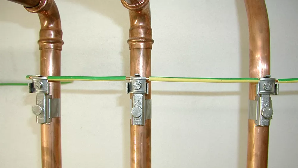
- Electrical Installations: Connect metallic parts to the main earthing busbar for increased safety.
- Lightning protection systems: Avoidance of dangerous potential differences due to lightning currents in accordance with IEC 62305.
- Data and IT systems: Reduction of interference caused by low-impedance connections.
- Industrial plants: Protection of machines and control systems against unwanted potential shifts.
- Hospitals and data centres: Ensuring stable operating conditions and avoiding interference with sensitive equipment.
For equipotential bonding, a foundation earth electrode is the most effective supplement, as it achieves the necessary values in the most economical way. In general, properly designed equipotential bonding is indispensable for the electrical safety of a building. Therefore, consider it during planning. Retrofitting is usually only possible with high financial and construction costs.
How equipotential bonding works
These measures ensure an even distribution of electrical potentials:
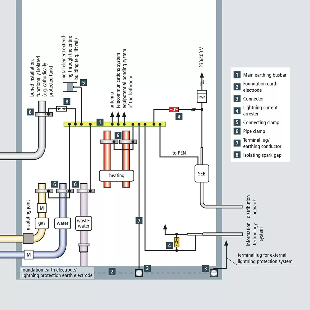
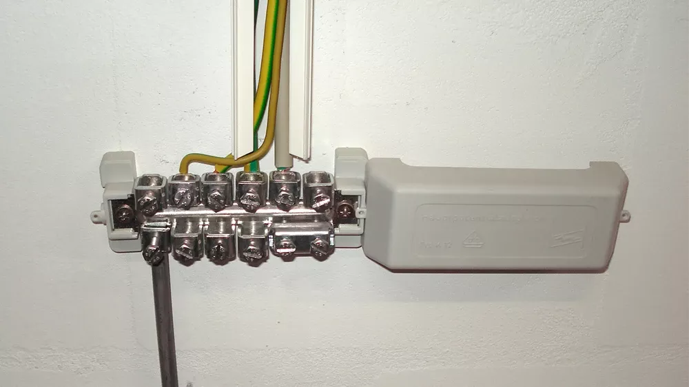
Protective equipotential bonding: All metal building parts, protective conductors, lightning protection systems and earthing systems are connected to a central equipotential bonding bar (the main EBB). This ensures that there are no dangerous voltage differences.
Additional equipotential bonding: In electrical installations with increased susceptibility to interference or strict safety requirements, additional connections are created to minimize interference.
Meshed equipotential bonding: In areas with sensitive electronics (such as data centres or industrial plants) a finely meshed network of conductive connections can be used to ensure constant potential distribution.
Low-resistance and low-impedance connections: The use of conductors over a large area with low resistance ensures effective current dissipation, especially in the case of high frequencies or lightning currents.
Surge arresters (surge protective devices, or SPDs) also play a decisive role in equipotential bonding for protection against transient overvoltages caused by lightning strikes or switching operations. They dissipate dangerous voltage peaks to earth in a controlled manner and ensure that electrical equipment and devices are not damaged.
Explained in simple terms: low resistance and low impedance
Low resistance refers to DC resistance. Low-resistance equipotential bonding means that the resistance is as low as possible to minimize voltage differences between different earth connection points.
- Particularly effective at low-frequency currents, such as mains alternating currents (50 Hz) or direct currents
- Typically used for connections in close proximity (≤10 m) to the main earthing busbar
- It is particularly suitable for retrofitting earthing systems; e.g. by connecting earth rods
Low-impedance also takes into account the AC components (AC), in particular the inductance and capacitance of a conductor. Low-impedance equipotential bonding is effective over a wider frequency range, including high frequencies. These can have a high impedance despite low resistance, resulting in unwanted voltages and interference.
- It is usually realised in the floor slab and helps to reduce stray currents in the electrical system.
- Preferred design for new buildings, especially in buildings with multiple grid connections or networked systems.
- Can be realised by means of an "L" design in concrete or a combined equipotential bonding system (CBN) with defined mesh sizes.
- Additional fixed earthing points allow low-impedance integration of equipment into the equipotential bonding and earthing system.
For optimum earthing and EMC safety, the equipotential bonding should be both low-resistance and low-impedance.
Equipotential bonding network
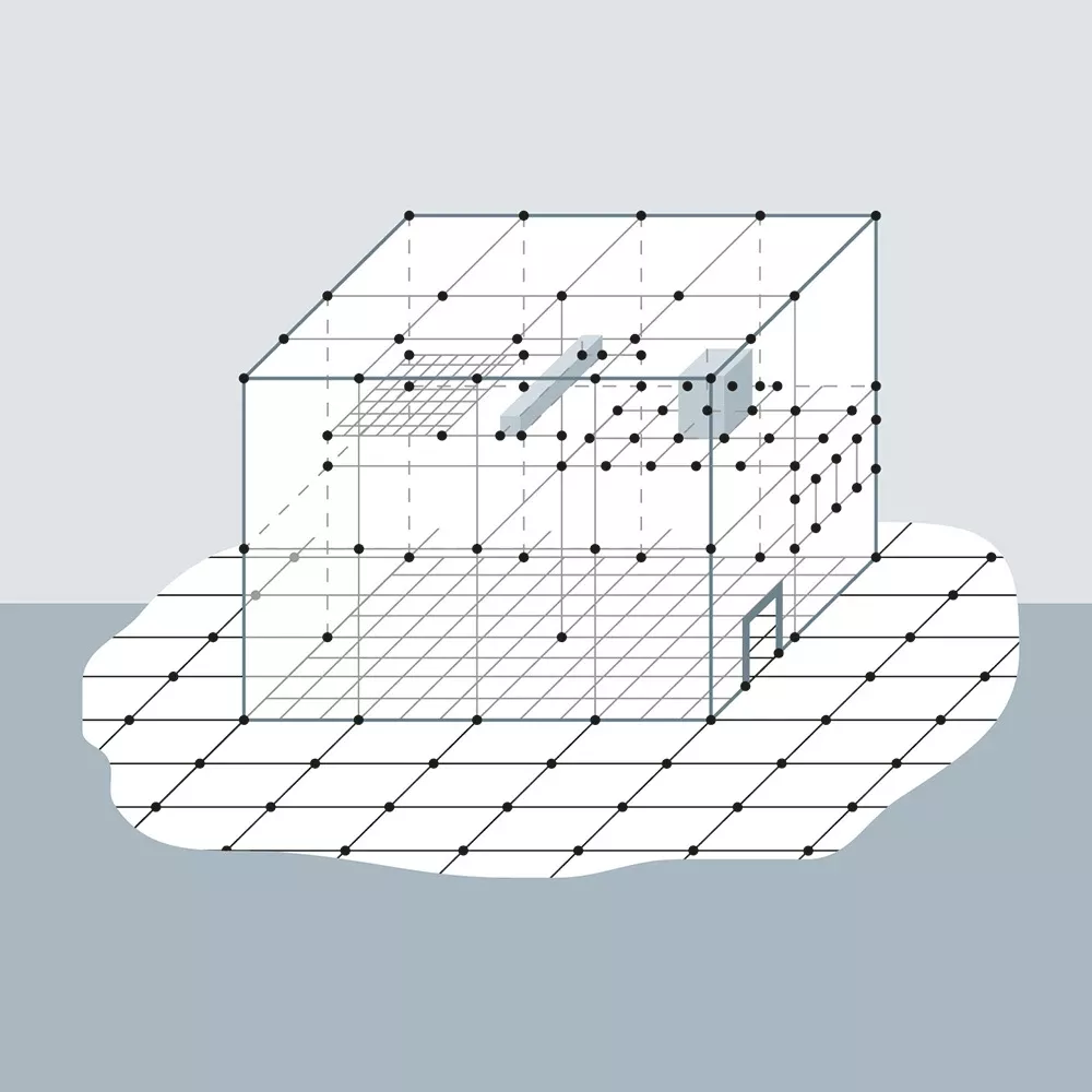
An equipotential bonding network establishes the electrical connection between all metallic parts of a building as widely and as low-impedance as possible – in the form of a three-dimensional intermeshed network. This is particularly used in industrial plants, hospitals, data centres and buildings with sensitive IT systems to minimize high-frequency interference, voltage peaks and electromagnetic coupling.
Structure of an equipotential bonding network:
- Comprehensive meshed earthing (for example, from copper strips or conductive structures in the floor)
- Multiple connection points to the equipotential bonding bar (EBB)
- Radial or intermeshed cable routing to avoid ground loops and voltage differences
- Additional earth connection points for IT and communications systems
These measures ensure that there are no unwanted potential differences between different areas of the building, especially at high frequencies or surges caused by lightning strikes.
These standards define how equipotential bonding must be implemented in various building types and installations:
- IEC 60364-5-54 specifies requirements for earthing systems and protective conductors
- IEC 62305 for lightning protection
- IEC 50310 covers the application of earthing and equipotential bonding measures in buildings with information technology equipment
Important terms relating to equipotential bonding
Supplementary equipotential bonding
May be prescribed in certain cases, for example if the circumstances present an increased electrical hazard, for example in swimming pools or potentially explosive atmospheres, as an additional or substitute measure for the automatic shutdown of the power supply and in IT systems with insulation monitoring.
Our services
We can provide support for your project from the planning to the implementation and beyond. Take advantage of our wide range of practical tools and services.
We create the entire lightning protection concept – from the risk analysis and earthing simulation to budget planning – all precisely tailored to your project and standard-compliant.
Design the external lightning protection and earthing systems for your project in accordance with DIN 18014 and IEC 62305-3. The program automatically creates a bill of materials for further use.