RAC spark gap technology
Maximum safety for electrical installations
Know-how from DEHN you can rely on: Rapid Arc Control (RAC) is a state-of-the-art spark gap technology that is used in surge protective devices for power supply systems. Do you need to reliably protect systems from the dangerous consequences of lightning currents and mains follow currents? Then find out more about RAC technology.

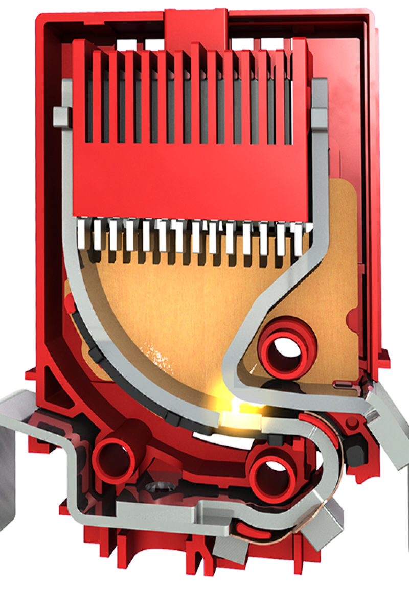
This is how the RAC spark gap technology works
The discharge process inside the RAC technology is split into three steps:
Maximum protective effect and efficiency
The internal lightning protection system conducts the lightning current introduced into the installation via the earthing system out of the object to be protected in the best possible way via the mains cable coming from outside. With RAC technology, most of the energy input flows through the RAC spark gap. This preserves connected equipment and systems that can only withstand minimal residual energy for a very short time.
Protection of installations
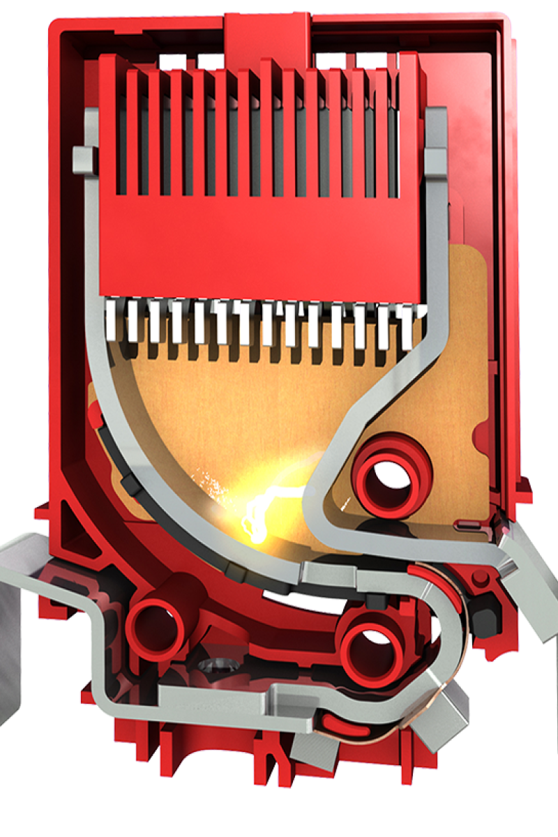
The RAC technology developed by DEHN significantly reduces the energy input compared to other solutions or technologies. Even with the highest energy inputs, for example from direct lightning strikes. This protects the downstream system and ideally extends its service life. This is possible because the RAC spark gap has a voltage-switching characteristic. This suddenly reduces the surge to a so-called "arc voltage", which is within the range of the nominal voltage.
Efficient arresters
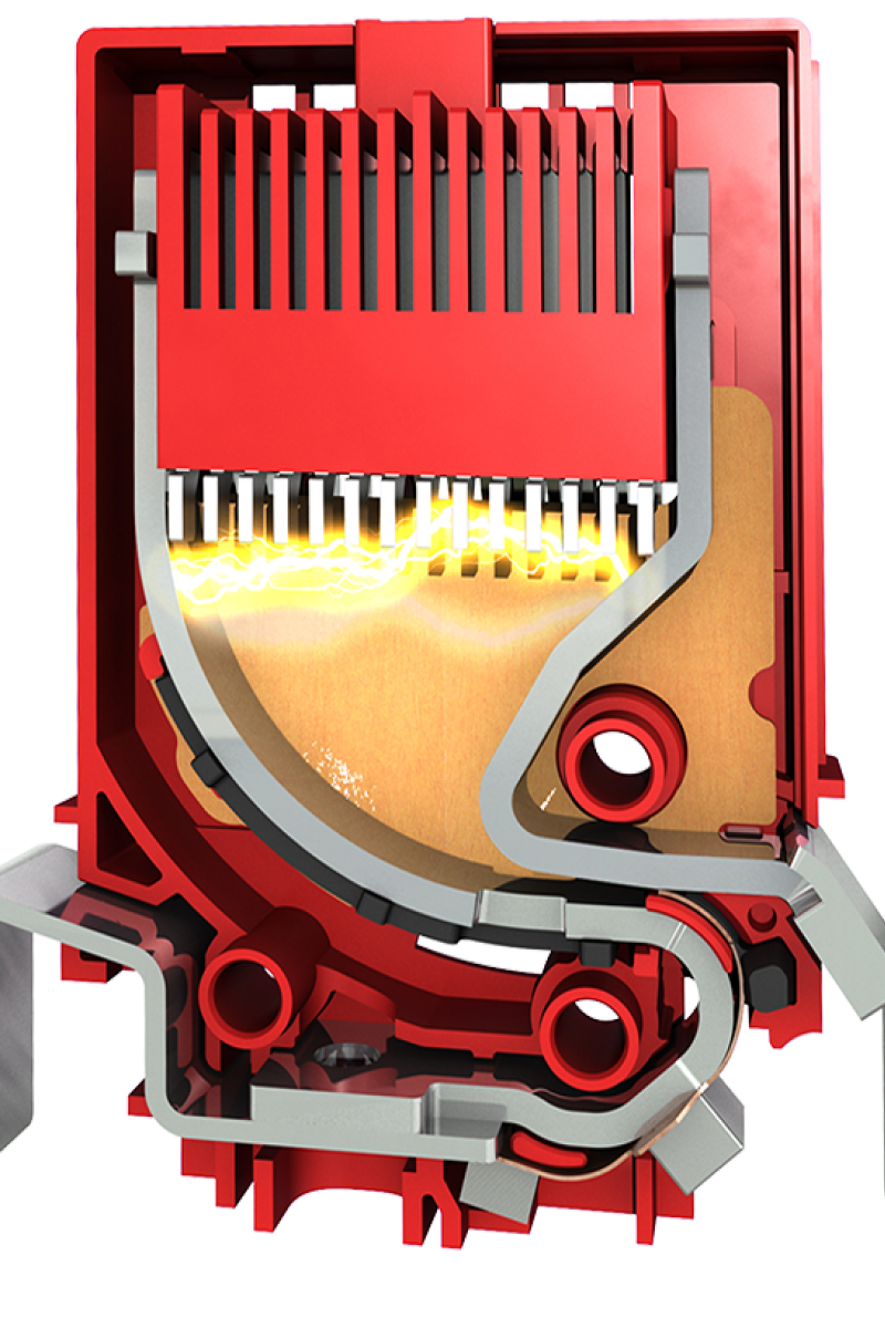
An arrester is maximally efficient if no energy is fed into the installation to be protected and the isolation criteria are fully met. RAC technology comes very close to this ideal situation.
RAC technology in use
Spark-gap-based, Type 1 + Type 2 combined arresters provide lightning equipotential bonding and terminal equipment protection in just one arrester stage.

DEHNventil modular
Multipole, modular combined arrester for protecting low-voltage consumer installations against surges with a follow current extinguishing capability of 100 kArms, even in the event of direct lightning strikes.

DEHNshield
Application-optimised multipole combined lightning current and surge arrester which ensures compact lightning equipotential bonding including protection of terminal equipment.

Further products
with RAC spark gap technology can be found in the product database.
Downloads
DEHNventil M2
DEHNventil M2 with RAC spark gap technology